Dev tools
How to create a 3D model of a real estate in Blender?
Create a 3D model of the real estate yourself and for free. This article describes how to create it in the free Blender software with the Archimesh add-on. You're done in an hour.
Digital 3D real estate models can be used in many applications for many purposes. This article is related to the creation of an interactive real estate configurator, see more in the article Interactive Virtual reality for real estate business - Advantages, possibilities, development.
Whether you get a 3D model of real estate from Photogrammetry or modeling from scratch, there's clear that in a greater or lesser extent you will not avoid a need of working even in a 3D modeling software where the preferred one should be choosed based on the project requirements and purpose. There're many great paid tools from Autodesk, ... and then there's the free open source 3D graphics editor Blender with a range of available add-ons, including architectural ones. Apart from great-looking photorealistic renders, it allows also to create great photorealistic action animations. And right this software is used for modeling described in this article.
[Note for beginners] Blender may seem relatively complicated at first glance for beginners. It has a bunch of cards, most functions instanciable via keyboard shortcuts, special control of the working desktop view, and finally - 99.9% of buttons and options about which you have absolutely no idea what they are for. Fortunately, there is documentation and a number of tutorials to help, but in the end, the best learning is by working in it. I didn't like Blender myself at first, but after a few hours I was orienting myself and everything started to make sense to me. If you did not done yet, I recommend to watch a few videos on YouTube about how to work in Blender and what it can do.
Creating a 3D model of an apartment in Blender
An exemplary real estate property for 3D modeling is a 2-rooms apartment unit with a total floor area of 70m², of which 16m² is a terrace - see floor plan and visualization.
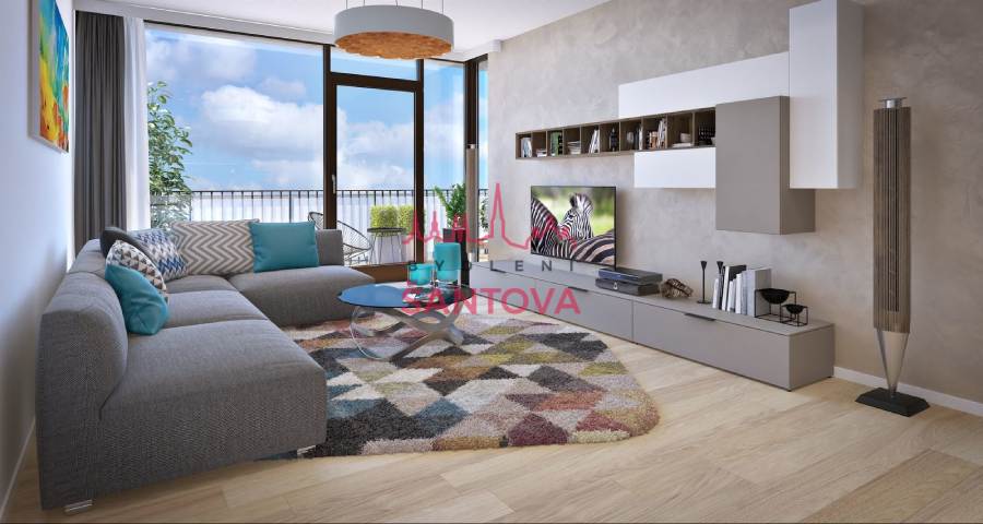
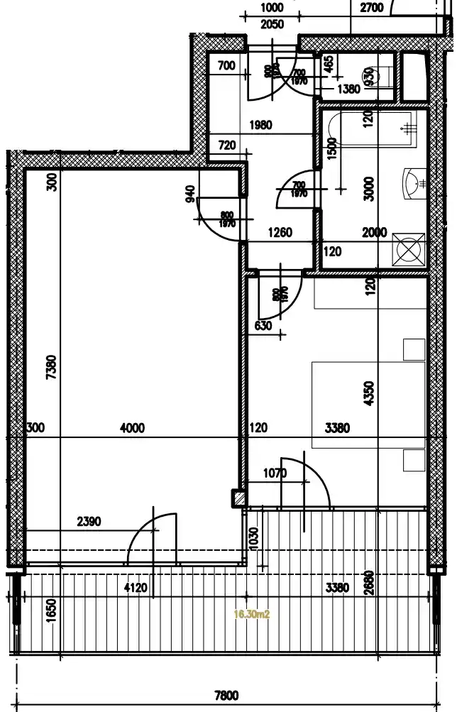

Data for modeling used from an illustrative image provided by developer + dimensional floor plan of the flat
Modeling procedure with Archimesh add-on
- Blender allows you to insert an image as a template in a plane (e.g. XY). Then it's easy to draw the walls based on the template. I didn't use it, I modeled from the scratch, only on the basis of the dimensions from the floor plan.
- For modeling I used the native add-on "Add Mesh: Archimesh" (it can be activated in "Edit → Preferences → Add-ons → Add Mesh: Archimesh)"
- I modeled to scale, with an accuracy of 1mm
- Archimesh objects can be inserted via "Add → Mesh → Archimesh → {specific object - eg Room}". Then the Archimesh tab are also available in the side menu (can be opened / closed with the "n" key) on the "Create" tab.
- I created the model gradually room by room. I started each in Archimesh by selecting "Room" and adding individual walls. Each room needs to be closed with 4 walls to generate a flawless floor and ceiling. In the case of common walls between two rooms, I set the visibility of one of the walls to "hidden". I did not take into account the different wall thickness (load-bearing, partition) within the model.
- Doors and windows are from the built-in Archimesh library. It is necessary to make sure that the position of windows, doors and other objects is set above the whole group of parts of the object. Once they are in place, a hole for them in the walls can be created by selecting their parent room object and pressing the "Auto Holes" button.
- I inserted floors and ceilings simply by checking the "Ceiling" and "Floor" buttons on the panel of individual rooms.
- The door is ajar by adjusting the z-axis rotation value on the door object of the door object group.
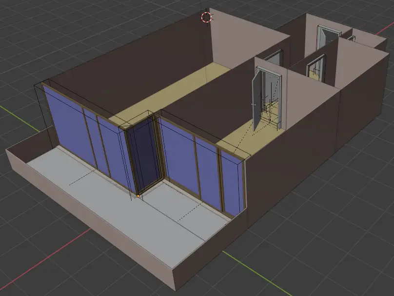
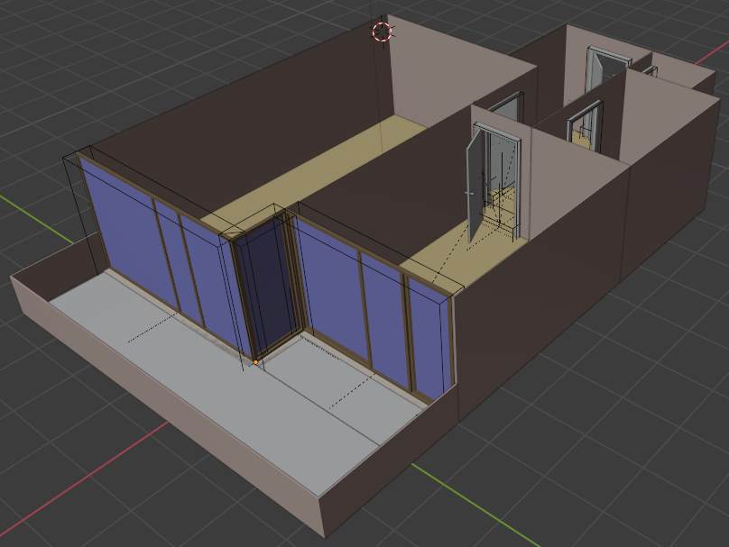
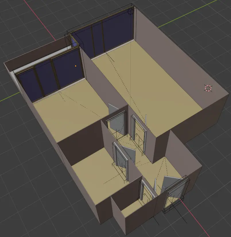
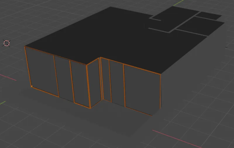
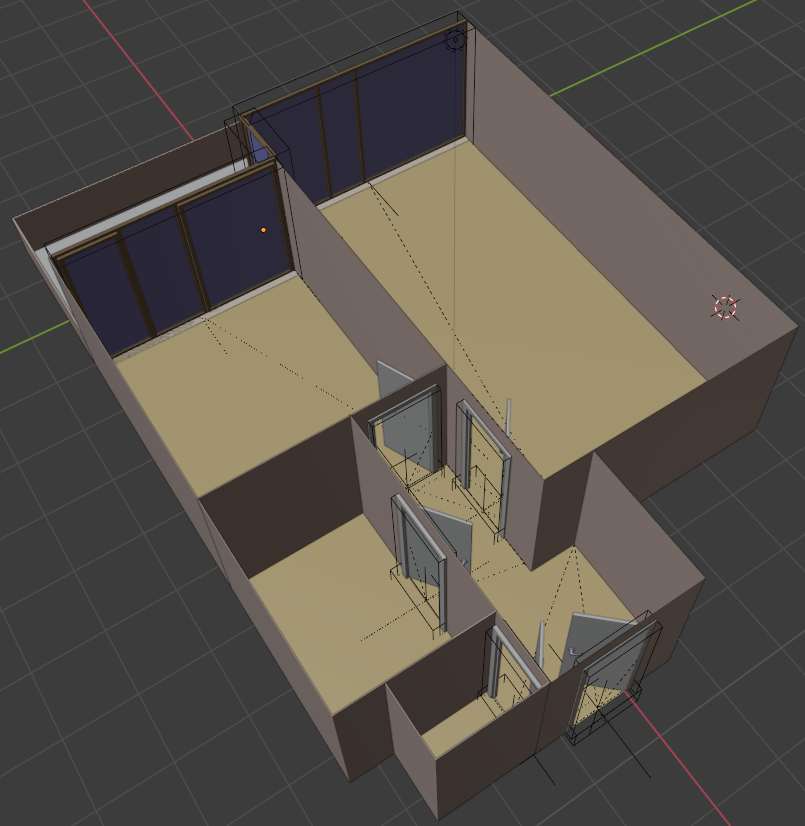 The result after less than an hour of working in Blender (View mode: Solid)
Modification of the rough model for future trouble-free export
Technical objects created by the Archimesh add-on
In the pictures of the apartment model above you can notice marking of technical objects (holes in walls) which were created together with placing doors and windows via Archimesh add-on. These technical objects are familiar for Archimesh and similar based extensions / add-ons, but if we would import the model into a different software including these objects, most likely the technical objects would be displayed as a solid white cube objects hiding the doors and windows themselves. This would happen regardless of set visibilityof the technical objects in Blender. To solve this issue, we can use one of the 2 following ways:
- By removing / hiding them in the external engine if they cause a problem
- By removing them in Blender before exporting the model
The appropriate type of solution depends on the future needs of working with the model. Let's say that, as part of work efficiency, you have exports from Blender automatically conencted with imports into follow-up softwares. It means that anytime you make a new export, the exported model is automatically reflected (loaded) in all softwares in which you work with the model.
The moment you perform the repair the first way, the problem will recur (and require repair) each time you make a new export. On the other hand, if you opt for the second solution, the problem will disappear permanently, but at the cost of losing a simple modification of the position of the objects through Archimesh (the door object will no longer be tied to the door hole object - the door hole will be a fixed non-movable part of the room object). However, there will still remain option to modify all needed with the help of common modeling tools in Blender (tab "modeling", option "Edit mode" on selected collection Object).
In this case, the fixed position of the doors and windows is already approved and cannot be interfered with, so the optimal solution is method 2. If the request for change nevertheless came, the adjustment would be made within the tools of common modeling. To process the repair in the second way, it is necessary to confirm the modifications made (inside window "Modifier properties" marked with blue service key icon) by the Archimesh tool for each modified object (room). After confirming all modifications (by "apply" button), all technical objects (in my case holes and base plates) can then be removed from the 3d model.
Visibility of model faces after export
Real-time graphics rendering is demanding on the graphics performance of the device. For this reason, most softwares and applications use optimization logic that ensures that rendering takes place only for the visible surfaces of the object. For this to work properly, each surface must provide information whether rendering is required for outside, inside, or both sides of a surface. The assignment of this information may differ across softwares, but usually it is set through "shader" or "normals" settings assigned to the object face. In Blender we use mainly settings of "normals" accessible in "Modeling" tab. To use it, simply select certain face of an object (you can do that in edit mode) and then go into "Mesh" → "Normals" and select the preferred option. If rendering from both sides is required, it may be activated in the material properties of the object (on the active object, in the materials bar - inside "Settings" window - check checkbox "Backface culling").
You can assign Normals to surfaces manually (shader settings can be recognized by a surface color in the "shading viewport"), or based on a test - make a test import to the follow up software, detect erroneously rendered surfaces, fix them in Blender and reexport again. An example of incorrect settings of Normals and how to correct them is explained below. (Some surfaces were set incorrectly by Blender, others were modified to incorect state by me to let me explain more states for you). Note - if you are not sure about surface visibility, look at it through the software camera object.

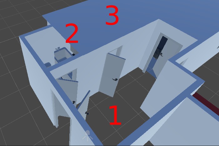 Example of incorrect Normals settings in Blender for export to Unity (View mode: Material preview)
In the example above, you can notice three surfaces with a wrong configuration:
- Missing floor render - Unity renders the area only from the view from bottom. To fix it, just switch the render from the bottom to the top of the surface ("Modeling" || "Mesh" → "Normals" → "Flip")
- The transparent wall between the rooms "toilet" and "bathroom" - although the wall may seem to be a solid object, in fact it's only a hollow block. Each side of the block has usually set default visibility from the outside only. In the case of the example, it seems be to set differently - the surface from the side of the toilet is not rendered which is caused by set inner normal for the surface. As a result, we see both walls to be transparent in the direction "Toilet" → "Bathroom" while from the opposite direction it all look ok. To fix this issue, we simply need set outer normals for the wall surface on the toilet side, which may be easily done by ("Modeling" || "Mesh" → "Normals" → "Recalculate Outside"), or through the shortcut shift + n.
- Point 3 seems clear now, does not it? If not, read further. If you are thinking why is not marked the ceiling of the room hallway or toilet which both are not visible instead of the visible ceiling marked by number 3, ask yourself - from what side a user see the surface when using the application? Yes, the user will be in the room, while you now see it from the top. To solve that, we simply need to flip normals of the ceiling plane object like in point 1 ("Modeling" || "Mesh" → "Normals" → "Flip"), or through ("Mesh" → "Normals" → "Recalculate Inside"), or even quicker by the keyboard shortcut shift + ctrl + n.
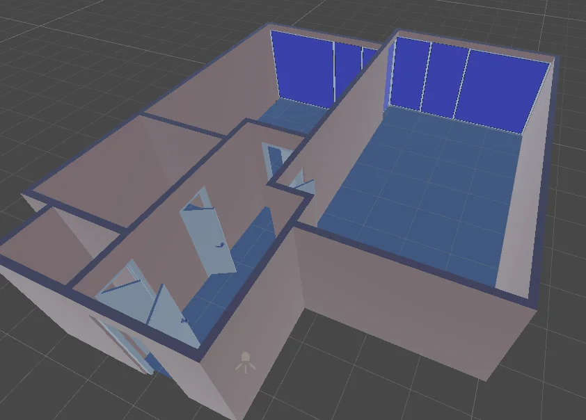
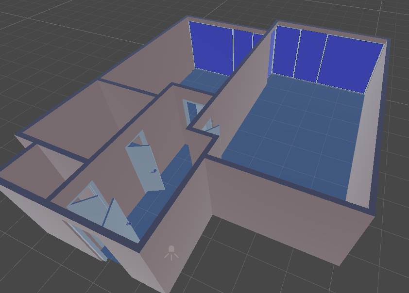 Example of error-free setting of normals in Blender after export to Unity - all surfaces are rendered on the right side. (display mode: Solid)
If our model differs from the floor plan due to the impossibility of creating a certain element in Archimesh, we can insert / edit it into the rough model using common modeling tools in Blender. In our model, the windows were modified in this way so that they fill the entire height of the property and at the same time naturally follow each other. Along with this modification, the number of vertices of the model was slightly reduced for lower performance requirements during its rendering.
 View of window objects after their individual modification using common modeling tools in Blender. (View mode: Render preview)
Configuration of the basic appearance - floors, walls, ceilings
The appearance of surfaces and entire objects is defined by the assignment of the material. It is defined by color, or more aesthetically - assigned texture or a combination of multiple textures with differently defined properties. This makes it possible to achieve a photorealistic appearance of the individual materials.
The apartment model will be situated in a clean design - white walls + floor with natural wood decor of unspecified appearance. The window frames are defined by an architectural design and will be in brown wooden decor. This gives a lift of the basic materials we need for the model. If we want to allow the user in virtual reality to compare / switch between multiple decors on individual surfaces, then it is necessary to have material for all available variants. In this case, especially the various floor decors - dark wood, light wood, etc.
If the textures for use in visualizations are not supplied by the supplier / manufacturer of floors / any components, various textures (wood, tiles, plaster) in various variations can be purchased / downloaded from specialized services.
Materials from textures and colors can be created / edited in the "Shading" tab in Blender. Its assignment to a specific object / surface is then simply - via the "Material properties" tab of the selected body / surface. We apply this procedure for the initial appearance of walls, ceilings, floors, doors, their handles and frames, window frames, railings and other residential components.
Apartment equipment - When to insert and from where?
The next step may be to add furniture to the model. For example, thousands of Cad and BIM models for free download are on the Polantis website. For example, furniture from popular Ikea stores can be downloaded at https://www.polantis.com/ikea. Various furniture can also be loaded directly into Blender through add-ons connected to various libraries of 3D models. The kitchen unit and other furniture can be modeled on the basis of the visualization provided by the kitchen / bathroom studio (visualization software of kitchen studios often allows 2D render to pdf and jpg format only), alternatively you can simply manage this furtniture through Home Builder asset library.
Adding furniture and other equipment to the model directly in Blender guarantees the possibility of creating great renders right in this software. When choosing furniture, however, we should take into account the purpose for which we intend to use the models. If it is a VR application, it is advisable to choose the best optimized models, or optimize them in terms of performance before exporting to the game engine. The export itself can be performed both for the whole object and separately for its individual parts. Anyway, before the export itself we should have chosen and tested transferring pipeline.
Pipeline for transferring 3D models across various software products
The term pipeline can be understood as is a procedure for secure transfer of 3D models between programs - for example, Blender for 3D modeling, Substance for material management and game engine (Unity / Unreal Engine) for processing VR applications.
In principle, there are 2 export options - 1) export the whole 3D model and 2) export the 3D model in separated parts. Option 1 is typically used for the first export, the way of next exports (updates) is usually driven by the capabilities and compatibility of the software and our needs. Within compatibility, it is important to know the behavior in the related software, into which the exported model is automatically imported (see the recommendations of work efficiency in the point of setting the visibility of the model faces). I will give an example on this model. Let's say that at Unity, we changed the floors and set up interactive elements - scripts and components for opening doors, turning on lights and the like. All these scripts and components are tied to the object in the 3D model in Unity. The question is, what does happen to these externally added elements when re-importing that model into Unity? In this case (export from Blender = import to Unity), while respecting the model names, nothing essential - the 3D model is updated, but without affecting the components connected to it. Within Unity, it does not matter whether we always export the whole 3D model or only its modified parts, if we make only minor changes.
This behaviour may vary across the software. At the same time, it is more time-consuming and opens up space for possible errors capable of drastically prolonging the development time. It is therefore safer and recommended by me to convert a 3D model between programs in logical parts - for example, individually parts of the apartment model (rooms) and then each piece of furniture separately, in its own .fbx or other file. In this case, you know exactly what has been imported and updated within the 3D model, and you can only check the relevant associated functionality in the imported part. Export of individual partial 3D models (components) from Blender is performed simply - by selecting the model → file → export → fbx to a file with the name of the given 3D model object located in the source folder of the software project into which we export the given model.
Texture management and their secure export
Textures associated with defined materials in Blender can be exported as part of the 3D model, or in the case of more complex materials more securely - separately. Separate export of textures for a specific object / whole project is performed by selecting the object(s) for which we want to export textures, and then selecting the file → External Data → Unpack All Into Files option. Selected output folder for the textures export should be the same as the one into which we export the 3d model itself - onlyby this way we keep the maximum simplicity.
When exporting individual models, it is necessary to strictly adhere to the same selected scale and ideally also the coordinate XYZ orientation of the model in space.
Following work with the 3D model in follow-up programs
The existing model is the basis for following work leading to countless number of uses of the model in many use-cases. For an example of creating an interactive virtual real estate tour, usable in the sense of a real estate interior configurator, a place for people meeting together (teambuildings) and regular interactive virtual tours, continue to the article Interactive Virtual reality for real estate business - Advantages, possibilities, development.